Understanding the concept | Finite Element Method | Advantages of FEA | Disadvantages of FEA | Applications of FEA | Finite Element Analysis
Watch videoFinite element analysis is a great method to solve complex engineering problems.
Before we start with the concept of Finite element analysis (FEA), let us understand FEA practically.
Finite Element Analysis (FEA) - Practical Approach:
→ Let us assume that you are a Design Engineer working in a car company.
→ Your role is to design a car.
→ While designing a car you should not only cover up the outer body shape and geometry, i.e., Aesthetics.
Designing (for car component) means to derive the dimensions (parameters) require to generate a car component with given constraints and based on affecting forces/loads and/or moments.
→ So, you start by deriving force and moments acting on different components of the car while designing.
→ But, to set the limit or capacity to withstand specific load/moment for the car depends on the material of the components of the car.
→ Materials have their own Ultimate tensile strengths (UTS) and Yield strengths (exceeding UTS after some limit results in failure).
→ So, important step in designing is the selection of material.
→ After you calculate the parameters based on forces and moments based on materials, you need to test its design by doing testing of the components.
Testing is the crucial process to check design of the components after its final manufacturing or in-between fabrication by applying same or more loads/moments on the components as per design.
→ This process of first time trail of a component after designing and manufacturing is known as Prototyping.
→ This will upon testing gives you the result as the valid proof of designed component upon applying pre-assumed loads/moments. You will find the result as feedback for your design. You may get success or failure based on application of loads/moments on the component.
→ After getting results, you can update design and can again go for prototyping.
→ All this process are like a loop - to get optimized, efficient and cost-effective product. This in simple words known as Research and Development (R&D) for/of the product.
→ Research and Development is a time consuming and costly process as to get optimized results you have to improve the design and product based on prototyping again and again.
→ To get this simplified we start using computers for iterations in design calculations.
→ With the development in the industrial sectors, man develops great simulation softwares like Ansys., PV-Elite, Solid works simulation, Solid Edge simulation, and many others.
Simulation is the process of generating required environment (means to help designer to constraint the designed component along with application of loads and/or moments) for testing the designed component.
→ This process of simulation of designed components in computers helps in very magical way for prototyping by reducing time as well as cost of prototyping.
→ Now, the point to explain the whole concept this way practically is because all these softwares uses the method known as Finite Element Method (FEM).
→ Let us understand the method which became revolution in the field of Designing (impacting prototyping).
Concept of Finite Element Analysis (FEA):
→ For simple engineering problems we always use analytical methods, which uses mathematical expressions that gives us unknown quantity at any location in a body/structure.
→ As a limitation of such methods, it is valid for infinite number of locations in body/structure.
→ But, for many complex engineering problems, it becomes very difficult or impossible to obtain analytical solutions. In such cases, the method known as Finite Element Method (FEM) is used.
Finite Element Method (FEM):
→ In Finite Element Method, the body/structure is divided into finite number of smaller units known as elements.
→ This process of dividing whole body into finite number of elements is known as discretization or meshing.
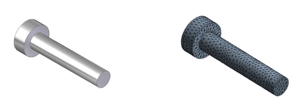 Fig-1: Discretization or Meshing
→ As shown in fig-1 above, we have stepped shaft at the left side and upon discretization (meshing) we get something like on right side.
→ The assemblage of these elements then represents the original body or structure.
→ These elements are considered to be interconnected at joints which are know as nodes.
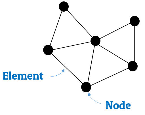 Fig-2: Illustrating nodes in elements
→ As we can see in the fig-2, which is the detailed view of mesh; we have triangular element mesh and all the elements are connected by dot like junctions known as nodes.
→ In FEM, solutions are formulated for each element and then combined to obtain the solution for the original body/structure.
→ This approach is known as "going from part to whole."
→ In order to make analysis more simpler, it is only at nodes where the continuity or equilibrium equations are required to be satisfied.
→ In FEM, the amount of data to be handled is dependent upon the number of elements into which original body/structure is discretized.
→ For large number of elements, it is formidable task to handle the volume of data manually, and hence use of computer is evitable in such cases.
→ As we are satisfying equilibrium/continuity equations at the nodes of the elements, the accuracy of the solution increases with the increase in the number of elements (fine mesh).
→ However, more number of elements results in increased computation.
Boundary Conditions:
→ In boundary value problems, a solution is sought in the region of the body/structure, while the values of certain variables are prescribed on the boundaries of the region.
→ The values of variables prescribed on the boundaries of the region are called as boundary conditions.
Types of Boundary Conditions:
Geometric (Essential) Boundary Conditions
Force (Natural) Boundary Conditions
Let us discuss them in detail with examples.


1. Geometric (Essential) Boundary Conditions :
-
In structural mechanics problems, the geometric boundary conditions includes prescribed displacements and slopes.
-
These are also known as kinematic boundary conditions
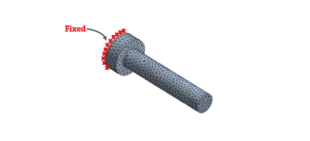 Fig-3: Geometric boundary conditions
- As we can see in the above figure, the stepped shaft is fixed from the one end.
- This is the boundary condition provided to shaft to constraint its position in the space.
- This kind of boundary conditions which is related to geometry, are geometric boundary conditions.
2. Force (Natural) Boundary Conditions :
-
In structural mechanics problems, the force boundary conditions includes prescribed forces and moments.
-
These are also known as static boundary conditions
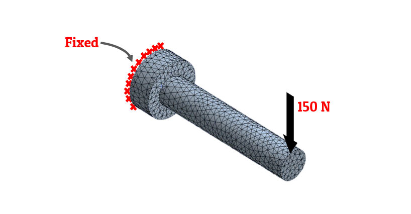 Fig-3: Force boundary conditions
- As we can see in the above figure, load of 150N is applied to one end of the fixed shaft.
- This is the boundary condition provided to shaft simulating the load acting on the shaft.
- This kind of boundary conditions which is related to loadings, are force boundary conditions.
Advantages of Finite Element Analysis (FEA):
→ The physical problems which were so far insolvable and complex for any closed bound solutions can be analyzed by using this method.
→ This method can be efficiently applied to bodies (or structures) with irregular geometry.
→ This method can take care of any type of loadings.
→ It can deal with any kind of boundary conditions.
→ This method can deal with material anisotropy and non-homogeneity very easily.
Disadvantages of Finite Element Analysis (FEA):
→ The accuracy of results from this method highly depends upon the degree of discretization.
→ Manual judgement is essential in discretization process.
→ Finite element analysis requires large computer memory and time, and hence cost involved is high.
→ In this method, errors in the input data may go undetected and erroneous solution obtained therefrom may appear acceptable.
→ This method is complicated and so not useful for simple problems.
Applications of Finite Element Analysis (FEA):
→ This method was originated for the solution of structural problems (structural analysis).
→ However, the theory on which it is based has made possible its successful application for the solutions of complex problems in other fields of engineering such as:
Mechanical design, mechanical vibrations, aeronautical engineering, heat transfer, fluid flow, soil and rock mechanics, bio-engineering, etc.
→ The different analysis that can be carried out using finite element analysis are:
Comments:
All comments that you add will await moderation. We'll publish all comments that are topic related, and adhere to our Code of Conduct.
Want to tell us something privately? Contact Us
Post comment