Concept of Direct and Reverse Crank for V-engines & Radial engines
Watch video
-
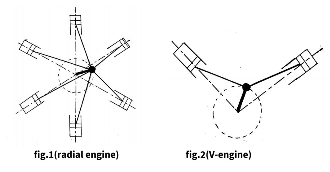
The method of direct and reverse cranks is applicable on reciprocating engines i.e V engines, radial engines, etc in which the piston performs reciprocating motion.
-
As shown in fig.1 (radial engine) and fig.2 (V-engine), the connecting rods are connected to a common crank and this crank revolve in one plane only. Hence there is no primary or secondary couple. Only primary and secondary force are required to be balanced.
- The method of direct and reverse crank is used in reciprocating engines for two purposes :
(1) For determining the primary and secondary unbalanced forces.
(2) For balancing the primary and secondary unbalanced forces.
- Fig.3 shows a reciprocating engine mechanism in which crank OC rotates at an angular speed of rad/s in a clockwise direction. Let be the angle made by crank OC with the line of stroke of cylinder.
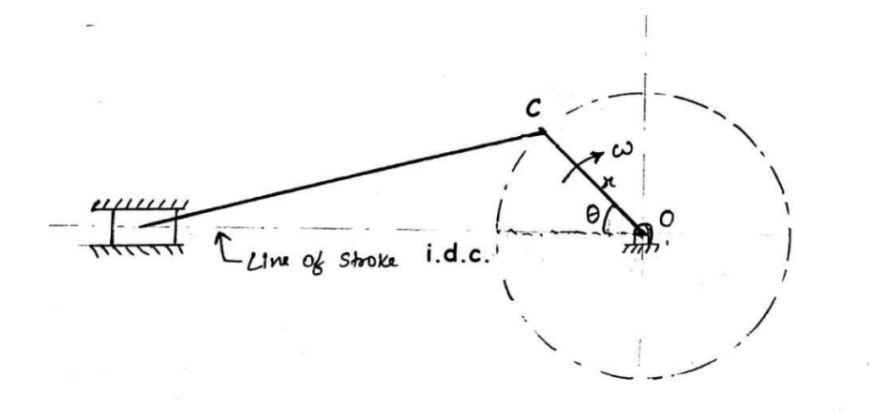 Fig-3
Fig-3
1. Primary force:-
- The unbalance primary force is given by,
where, m = mass of reciprocating parts, kg
- This unbalanced primary force is equal to the horizontal component of the centrifugal force produced by the imaginary mass ‘m’ placed at crank pin ‘C’, as shown in fig.4.
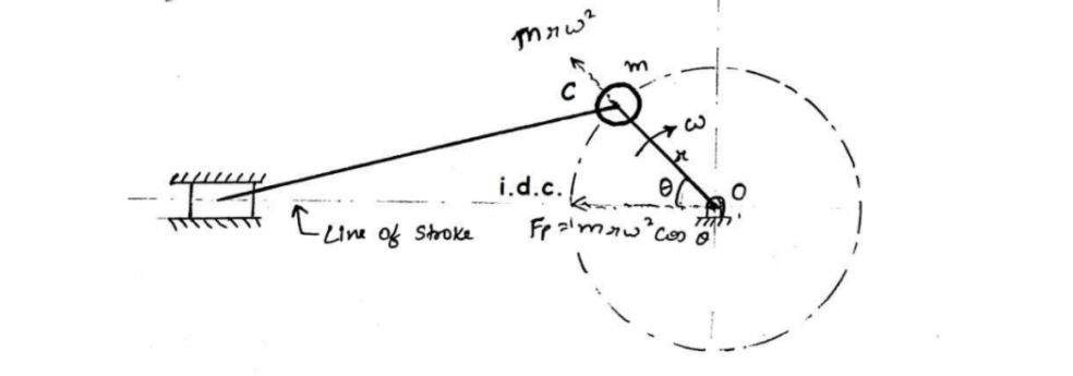 Fig-4
Fig-4
- The arrangement shown in fig.4 can be replaced by another arrangement, shown in fig.5, in which OC is called as the actual crank or primary direct crank and OCˊ is called the indirect crank or primary reverse crank.
- The unbalanced primary force due to ‘m’ mass can be determined by replacing mass each at the mirror image and this method of replacing ‘m’ mass with mass is called direct and reverse crank method.
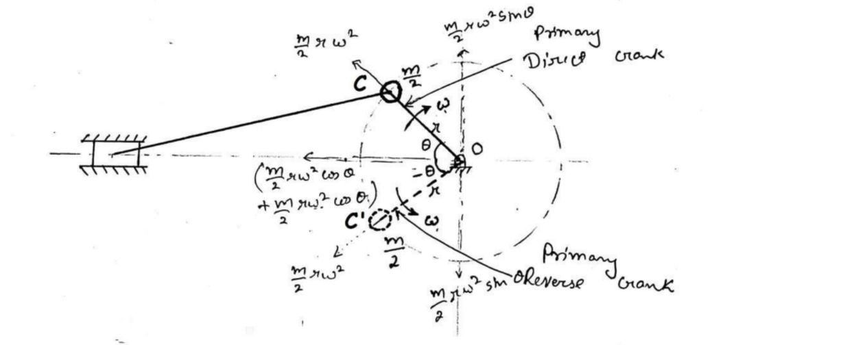 Fig-5
Fig-5


-
The primary direct crank OC makes an angle with line of stroke and is rotating uniformly at ‘’ rad/s in clockwise direction whereas the primary reverse crank OCˊ makes an angle - with line of stroke and is rotating uniformly at ‘’ rad/s in anticlockwise direction as shown in fig.5. Thus the primary reverse crank is mirror image of the primary direct crank.
-
The parameters of primary direct and reverse cranks:
I. Primary direct crank:
Angular position =
Angular velocity = (clockwise)
Radius of crank = rII. Primary reverse crank:
Angular position = -
Angular velocity = (anticlockwise)
Radius of crank = r
-
Let mass ‘m’ of reciprocating parts is divided into two equal parts (i.e. ).
One of the parts is placed at direct crank pin ‘C’ and the other part is placed at reversed crank pin ‘C’ as shown in fig.5. -
Centrifugal force acting on each mass placed at direct crank pin C and reverse crank pin
- Component of centrifugal force acting on the mass placed at point C, along the line of stroke
- Component of centrifugal force acting on the mass placed at point Cˊ, along the line of stroke
- Total component of the centrifugal force acting along the line of stroke
- This total component of the centrifugal force acting along the line of stroke, is equal to primary unbalanced force,
-
Hence, for determining the unbalanced primary force, the mass ‘m’ of the reciprocating parts can be replaced by two masses i.e. each at point C and Cˊ respectively.
-
The vertical components of centrifugal force of masses () placed at point C and Cˊ are equal to , so these components are equal in magnitude and opposite in direction to each other. Hence, these components are balanced.
2. Secondary force:
- The unbalanced Secondary force is given by,
- We can find this secondary unbalanced force by using direct and reverse cranks method.
- For determining unbalanced secondary force, the mass ‘m’ of the reciprocating parts is replaced by two masses equal to at crank pins of secondary direct crank and secondary reverse crank (i.e. at point C and Cˊ) such that secondary direct crank is making an angle 2 and secondary reverse crank is making an angle -2 with line of stroke as shown in fig.6.
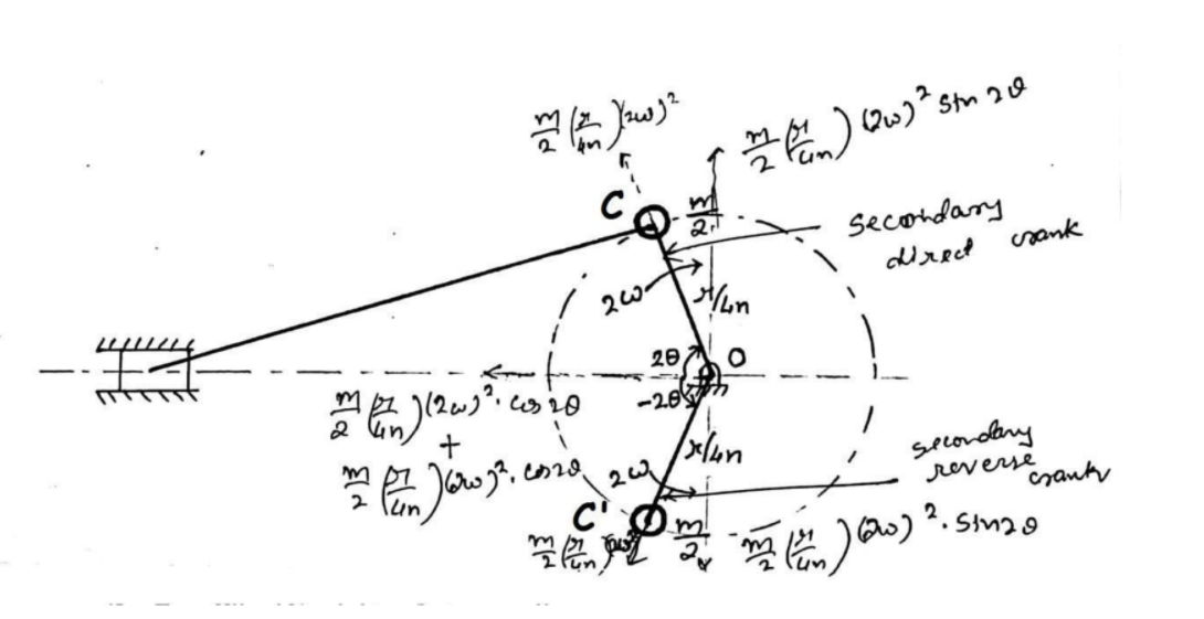 Fig-6
Fig-6
- The parameters of secondary direct and reverse cranks:
I. Secondary direct crank:
Angular position = 2
Angular velocity = 2 rad/s (clockwise)
Radius of crank =II. Secondary reverse crank:
Angular position = -2
Angular velocity = 2 rad/s (anticlockwise)
Radius of crank =
Also read these important notes:
Suggested Notes:
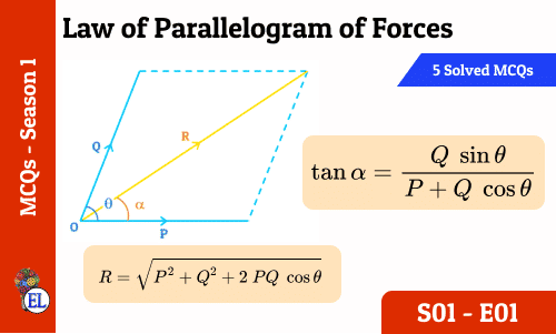
Law of Parallelogram of Forces : 5 in 5 MCQs S01-E01
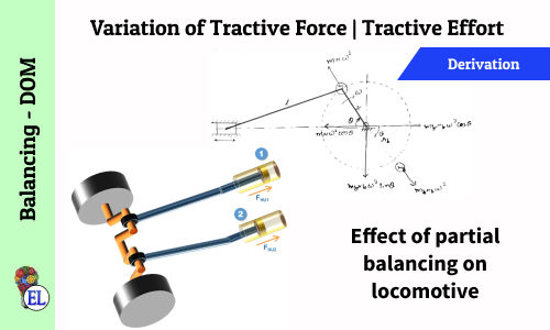
Variation of Tractive Force | Tractive Effort | Effect of Partial Balancing of Locomotives
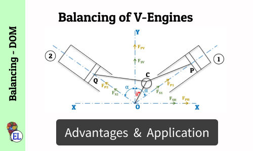
Balancing of V-Engines
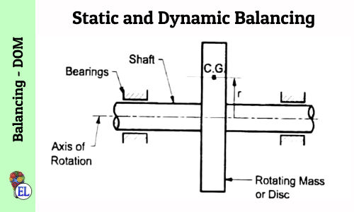
Static and Dynamic Balancing
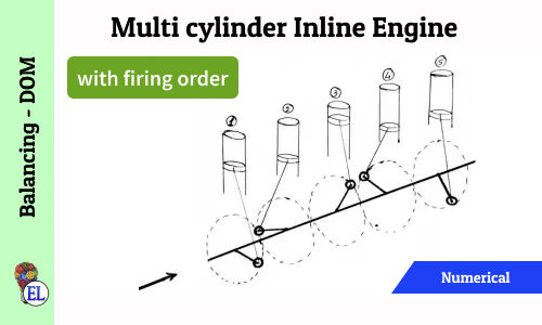
Multi Cylinder Inline Engine (with firing order) | Numerical
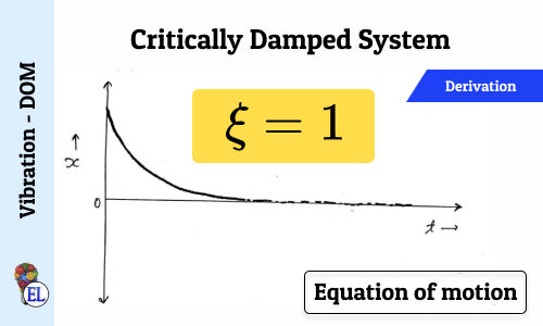
Critically Damped System (ξ = 1)
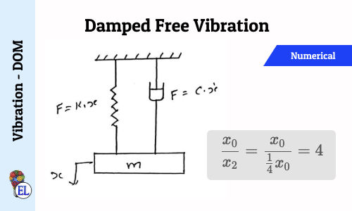
Damped free Vibration - Numerical 1
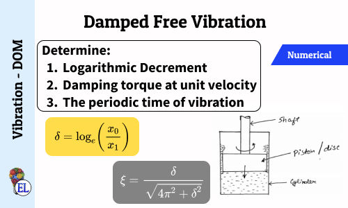
Damped free Vibration - Numerical 2
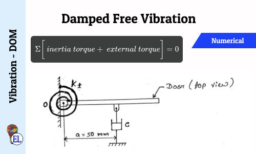
Damped free Vibration - Numerical 4
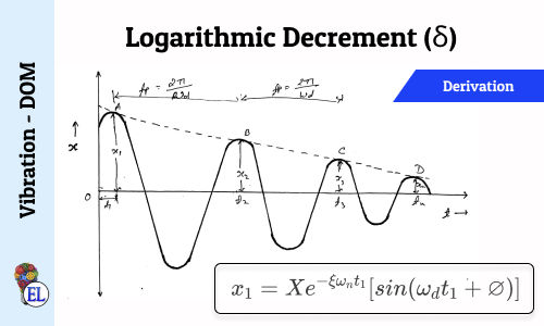
Logarithmic Decrement (δ)
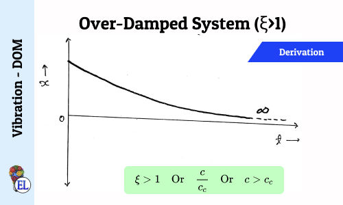
Over-Damped System (ξ>1)
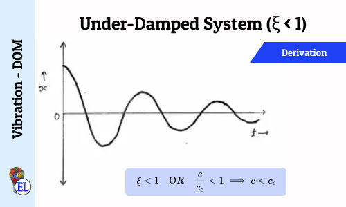
Under-Damped System (ξ < 1)
Suggested Notes:
Law of Parallelogram of Forces : 5 in 5 MCQs S01-E01
Variation of Tractive Force | Tractive Effort | Effect of Partial Balancing of Locomotives
Balancing of V-Engines
Static and Dynamic Balancing
Multi Cylinder Inline Engine (with firing order) | Numerical
Critically Damped System (ξ = 1)
Damped free Vibration - Numerical 1
Damped free Vibration - Numerical 2
Damped free Vibration - Numerical 4
Logarithmic Decrement (δ)
Over-Damped System (ξ>1)
Under-Damped System (ξ < 1)
Comments:
All comments that you add will await moderation. We'll publish all comments that are topic related, and adhere to our Code of Conduct.
Want to tell us something privately? Contact Us
Post comment