Multi Cylinder Inline Engine (with firing order) | Numerical
Watch video
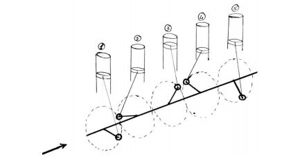 fig. 1
Basic knowledge about Firing Order
The firing order is a sequence of giving spark/firing to the cylinders of multi-cylinder inline engines. Firing order is provided in multi-cylinder inline engines in order to avoid vibrations (If firing order is not provided in multi-cylinder inline engines, then all the pistons will move in upward direction at the same time and same way they move in the downward direction at the same time. This creates a lot of vibration.) For avoiding these vibrations, firing order is provided in multi-cylinder inline engines.
Numerical
A four stroke five cylinder inline engine has a firing order of 1-4-5-3-2-1. The centre lines of cylinders are spaced at an equal interval of 15 cm, the reciprocating parts per cylinder have a mass of 1.5 kg, the piston stroke is 10 cm and the connecting rods are 17.5 cm long. The engine rotates at 600 rpm. Determine the value of maximum primary and secondary unbalanced forces and couples about the central plane.
Solution:
Given data:
The force and couple data is given in table:
| Plane | Mass (m), kg | Radius (r), m | Centrifugal Force (m x r), kg.m | Distance From R.P.(l), m | Couple (m x r x l), kg.m2 | Primary Crank Position 'θ' | Secondary Crank Position '2θ' |
|---|---|---|---|---|---|---|---|
| 1 | 1.5 | 0.05 | 0.075 | -0.3 | -0.022 | 0° | 0° |
| 2 | 1.5 | 0.05 | 0.075 | -0.15 | -0.011 | 576° i.e. 216° | 1152° i.e. 72° |
| 3 (R.P.) | 1.5 | 0.05 | 0.075 | 0 | 0 | 432° i.e. 72° | 864° i.e. 144° |
| 4 | 1.5 | 0.05 | 0.075 | 0.15 | 0.011 | 144° | 288° |
| 5 | 1.5 | 0.05 | 0.075 | 0.3 | 0.022 | 288° | 576° i.e. 216° |
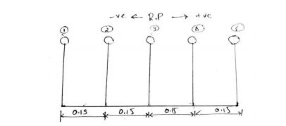 fig.2 (a) Position of planes
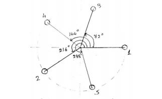 fig.2 (b) Primary crank positions
- Assuming the engine to be vertical, the position of cylinders are shown in fig.2(a).
- The angles are measured from cylinder 1.
- Cylinder 3 is considered as a reference plane (R.P.)
- The engine is working on a four stroke cycle, the angle between two crank
- Considering firing order : 1-4-5-3-2-1
1. Primary force polygon
For drawing a primary force polygon, take a suitable scale of 1 cm = 0.075 kg.m. From fig.2(c) it is seen that, primary force polygon is closed and hence there is no unbalanced primary force.
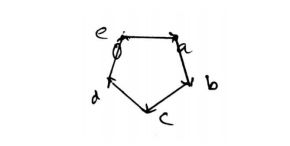 fig.2 (c) Primary force polygon
2. Primary couple polygon
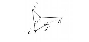 fig.2 (d) Primary couple polygon
- Draw the primary couple polygon by taking a suitable scale of . The vector represents the unbalanced primary couple .


- Now from fig.2 (d), measure ;
- Hence, the unbalanced primary couple is,
3. Secondary force polygon
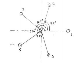 fig.2 (e) Secondary crank positions
 fig.2 (f) Secondary force polygon
Draw the secondary force polygon by taking a suitable scale of . From fig.2 (f), it is seen that the secondary force polygon is closed, hence there is no unbalanced secondary force.
4. Secondary couple polygon
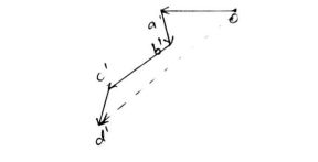 fig.2 (g) Secondary couple polygon
-
Draw the secondary couple polygon by taking suitable scale of . The vector represents the unbalanced secondary couple
-
Now from fig.2 (g), measure ;
- Hence, the unbalanced secondary couple is,
Suggested Notes:
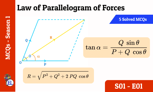
Law of Parallelogram of Forces : 5 in 5 MCQs S01-E01
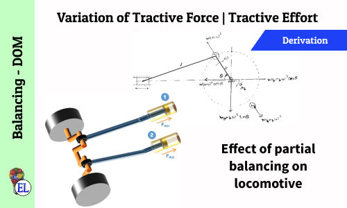
Variation of Tractive Force | Tractive Effort | Effect of Partial Balancing of Locomotives
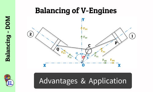
Balancing of V-Engines
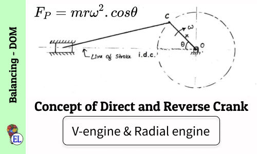
Concept of Direct and Reverse Crank for V-engines & Radial engines
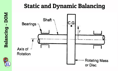
Static and Dynamic Balancing
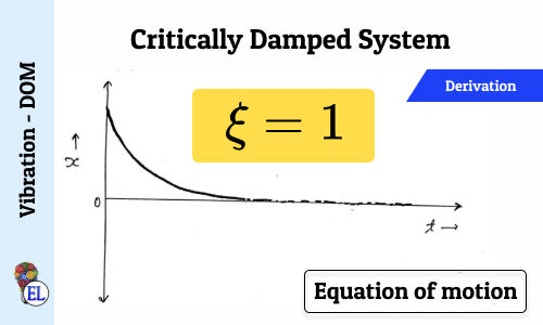
Critically Damped System (ξ = 1)
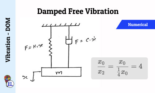
Damped free Vibration - Numerical 1
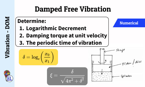
Damped free Vibration - Numerical 2
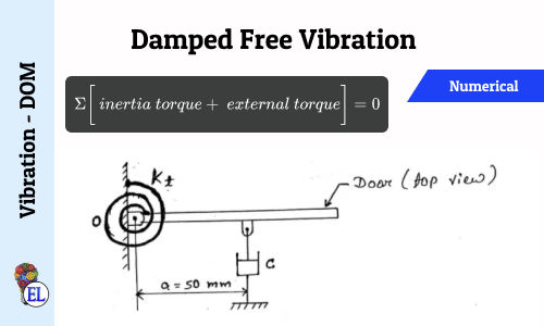
Damped free Vibration - Numerical 4
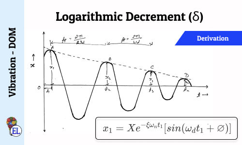
Logarithmic Decrement (δ)
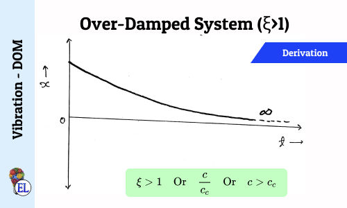
Over-Damped System (ξ>1)
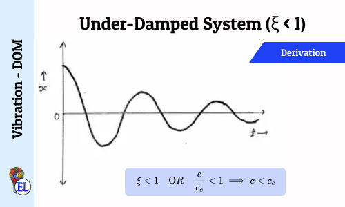
Under-Damped System (ξ < 1)
Suggested Notes:
Law of Parallelogram of Forces : 5 in 5 MCQs S01-E01
Variation of Tractive Force | Tractive Effort | Effect of Partial Balancing of Locomotives
Balancing of V-Engines
Concept of Direct and Reverse Crank for V-engines & Radial engines
Static and Dynamic Balancing
Critically Damped System (ξ = 1)
Damped free Vibration - Numerical 1
Damped free Vibration - Numerical 2
Damped free Vibration - Numerical 4
Logarithmic Decrement (δ)
Over-Damped System (ξ>1)
Under-Damped System (ξ < 1)
Comments:
All comments that you add will await moderation. We'll publish all comments that are topic related, and adhere to our Code of Conduct.
Want to tell us something privately? Contact Us
Post comment